Arty JTAG adapter
For those not afraid of grabbing a soldering irons from the wrong end, a more robust and easy to use alternative to the Adafruit coloured ribbon cable recommended in the Coreplex FPGA Evaluation Kit documentation is a small piece of prototyping PCB (the usual kind with many 0.1” spaced wholes) and two male headers, one 20 pins large JTAG header with insertion key and one 12 pins header with 90 degrees pins.
The 12 pins male header must be placed at the margin of the PCB, to be plugged into the Arty 90 degrees JD female receptacle.
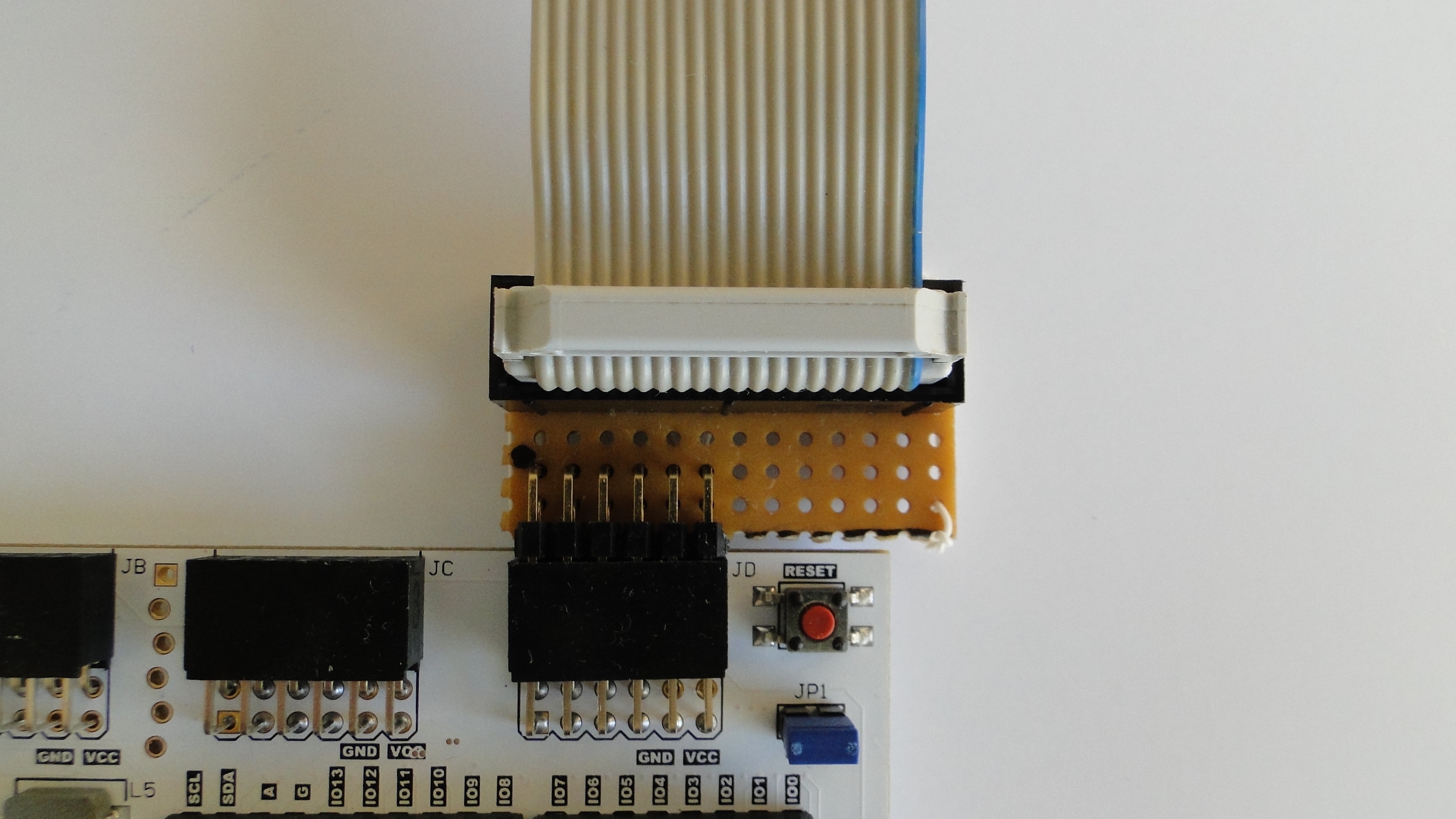
As seen from the bottom, where the wires are soldered, the small board looks like:
                          purple  1 *  o  7 yellow
     - 19 o  o 20 -       orange  2 o  o  8 green
     - 17 o  o 18 -         blue  3 o  o  9 grey
  grey 15 o  o 16 white        -  4 o  o 10 -
purple 13 o  o 14 black    black  5 o  o 11 white
     - 11 o  o 12 -        brown  6 o  o 12 red
  blue  9 o  o 10 -
 green  7 o  o  8 -
yellow  5 o  o  6 -
orange  3 o  o  4 -
   red  1 *  o  2 brown
The ‘square’ pins (#1) are marked with an asterisk.
The pins that must be connected together are marked with identical colours.
